Wednesday 14 September 2011

[Tool] Unit conversion tool for Instrumentation engineer.

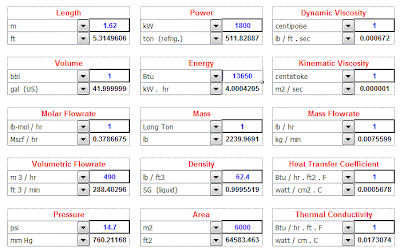
As an instrumentation engineer we have to do a lot of unit conversion. I got a very effective tool converting units. It is a not a software. It is an excel sheet. No need to install it but Microsoft office software must be installed in your computer for opening the tool.

You can convert the following units.

*Length
*Volume
*Molar power rate
*Volumetric flow rate
*Pressure
*Power
*Energy
*Mass
*Density
*Area
*Dynamic viscosity
*Kinematics viscosity
*Mass flow rate
*Heat transfer coefficient
*Thermal conductivity
*Heat flux
*Specific energy
*Specific Heat

Unit_conversion_tool


Download the Unit conversion tool.

I got the tool from Internet. If you are having such tools, share it..
READ MORE - [Tool] Unit conversion tool for Instrumentation engineer.

Saturday 10 September 2011

[Instrumentation Questions] What are process variables? and Define all the process Variable and state their unit of measurement?


What are the process Variables?
The process Variables are:
Flow.
Pressure.
Temperature.
Level.
Quality i.e. % O2, CO2, pH etc.

Define all the process Variable and state their unit of measurement. ?

Flow: Any fluids or liquids flowing from one place to another place is called flow and it is defined as volume per unit of time at specified temperature and pressure .Conditions, is generally measured by positive-displacement or rate meters.
Units: kg / hr, litter / min, gallon / min, m3 / hr, Nm3 / hr. (Gases)

Pressure: It is defined as Force per unit Area. P = F/A
Units : bar, Pascal, kg / cm2, lb / in2.

Level: The height of the water column, liquid and powder etc., at the desired measurement of height between minimum level points to maximum level point is called level. The measurement principle is, head pressure method.
Units: Meters, mm, cm, percentage.

Temperature: It is the degree of hotness or coldness of a body is called temperature.
Units : Degree Centigrade, Degree Fahrenheit, Degree Kelvin, Degree Rankin.

Quality: It deals with analysis.( pH, % CO2, % 02, Conductivity, Viscosity )
READ MORE - [Instrumentation Questions] What are process variables? and Define all the process Variable and state their unit of measurement?

Monday 5 September 2011

[Update] Deatailed explanation of "How to read a Piping and Instrument Diagram(P&ID)?"

This topic is already(Piping and instrumentation diagram) discussed in instrumentpedia. But now I feel that more explanation is required on this topic.That is why I decided to write a detail post about it.
For reading a piping and instrumentation diagram someone should be very much familiar with the symbols.We can classify the instruments in to three large families.
1.Locally mounted instruments.
2.Instrument present in the front end.
3.Instrument present in the back end(Not accessible by operator. This class of instrument is located in the controller.
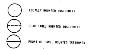
classification_of_instruments_in_piping_and_instrument_diagram

Each instrument is also identified by means of letters that describes its function as well as progressive numbers to ensure proper identification.

The first letter stands for the variable being measured.

T-Temperature
L-Level
P-Pressure
F-Flow
K-Time
S-Speed

Instrument function is represented by the second letter

I-Indicator
T-Transmiiter
R-Recorder
C-Control
D-Differential
S-Switch
E-Element
A-Alarm

Alarm function is represented by the third letter.

H-High
L-Low

Shutdown function is represented by the third and fourth letter.

H-Shut down due to a high value
L-Shut down due to a low value
HH-Shut down due to a high high value
LL- Shut down due to a low low value.

Letters used in Piping and instrumentation diagram
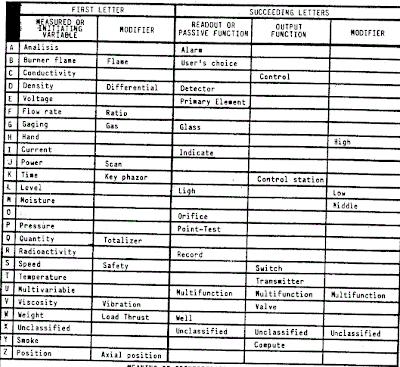
piping_and_instrumentation_digram_identification_letter_meaning

Some examples of instrument representation in piping and instrument diagram

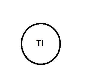
Locally mounted temperature Indicator
p&id_representation_of_field_mounted_temperature_indicator
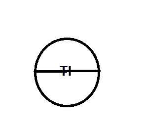
Panel mounted temperature Indicator.
p&id_representation_of_field_mounted_temperature_indicator
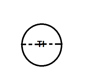
Temperature indicator in the DCS/PLC/Controller.
p&id_representation_of_controller_mounted_instrument
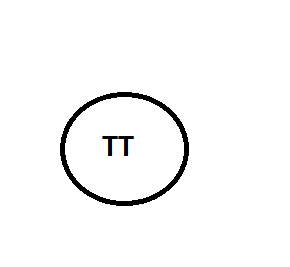
Locally mounted temperature transmitter.
p&id_representation_of_temperature_transmitter_field_mounted

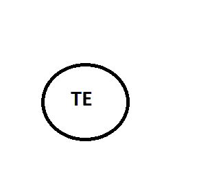
Thermo element representation(Thermocouple/RTD)
p&id_representation_of_temperature_element


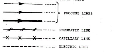
Representation of pipes and signal in P&ID:

Process lines
Pneumatic line
Capillary line
Electric line


piping_signal_represenatation

Control valves are representation in P&ID

LCV - Level control valve
PCV – Pressure control valve
TCV- Temperature control valve
FCV- Flow control valve
PSV- Pressure safety valve
ROV- Remote operated valve
MOV- Manually operated valve
FIC/V- Anti surge valve

Related post:
How to read a piping and instrument diagram?
Difference between p&id and pfd?
READ MORE - [Update] Deatailed explanation of "How to read a Piping and Instrument Diagram(P&ID)?"

Thursday 1 September 2011

Blog for Instrumentation, Electrical and Automation Engineers/Professionals

Hi Engineers/Professionals While starting this blog my intention was to share the knowledge with the others.. But now I decided to change the strategy.. Now I am planning to help the fresh engineers by giving some tips about interviews and giving some frequently asked interview questions.. Hey guys, what is your opinion?. Let me know?

Now onwards there will be a separate section for instrumentation and electrical interview questions. I have lot of instrumentation study materials. I am ready to share all those things. I need opinion of you guys.

Share this page with your friends and colleagues. This blog is exclusively for Instrumentation, Electrical and Automation Engineers/Professionals. Cheers!!!
READ MORE - Blog for Instrumentation, Electrical and Automation Engineers/Professionals
Powered by Blogger.
 
 
Copyright © Computer
2011 All Reserved
Devilzc0de Simple Template by Awang Shellovers