DP level transmitter with actual pressure

*Hook up HART Communicator and verify some parameters by refer to data sheet. Typical parameters are, tag number, PV, LRV and URV.
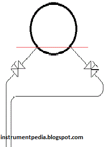
*Isolate the instrument from the process.
*Release both pressure and drain low side liquid only through manifold drain.
*PRECAUTION 1: During this process, please do not open the equalizing valve at the manifold.
*Open both plug at seal pot
*Top up the seal liquid for low side until half of seal pot.
*Remove the tubing at high side of the flange (not at the manifold side) to drain remaining liquid in equalizing tube.
*PRECAUTION 2: Do not remove the process fluid in B. Please ensure it is full with process liquid.
*Install back both plug and connect back tubing at high side of the flange
*Hook up a multimeter in series with the signal to the DCS to measure current signal.
*Open low side (top) isolation valve only and high side (bottom) isolation valve remain closed
Multimeter should show 4mA If not, do zero adjustment at transmitter using HART Communicator.
Isolate back low side (top) isolation valve and released the pressure through high side vent valve seal pot.
Close the vent at seal pot
*Fill up the equalizing tube until full with product by removed the top fitting and slowly open the isolation valve (high side) until the equalizing tube is full (or up to 100% level) with product. Close the high side isolation valve.
*Install back any fitting that was remove for filling up the equalizing tube
*Open low side (top) isolation valve only and high remain closed.Multimeter should show 20mA
If not, do span adjustment at transmitter using HART Communicator
Note:
The reason to open the low side (top) isolation valve is to get the actual pressure vessel
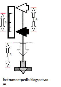
Example Calculation:
Product S.G=0.89
Glycol S.G = 1.02
A= 2000mm (measurement length)
B= 100mm (off set)
C=A+B=2100mm
Dp = pressure at high side – pressure at low side
LRV = (B x Product S.G) – (A x Glycol S.G)
= (100mm x 0.89) – (2000 x 1.02)
= 89 – 2040
= -1951 mmH2O
URV = (C x Product S.G) – (A x Glycol S.G)
= (2100mm x 0.89) – (2000 x 1.02)
= 1869 - 2040
= -171 mmH2O
Note:
LRV and URV calculation may have small variation as compare with HART communicator reading due to calibration with actual pressure.
Related Post:
Calibrate Displacer Type Level transmitter
Differential Pressure Level transmitter Capillary type
Flow transmitter Pitot tube
Differential Pressure Flow transmitter
*Isolate the instrument from the process.
*Release both pressure and drain low side liquid only through manifold drain.
*PRECAUTION 1: During this process, please do not open the equalizing valve at the manifold.
*Open both plug at seal pot
*Top up the seal liquid for low side until half of seal pot.
*Remove the tubing at high side of the flange (not at the manifold side) to drain remaining liquid in equalizing tube.
*PRECAUTION 2: Do not remove the process fluid in B. Please ensure it is full with process liquid.
*Install back both plug and connect back tubing at high side of the flange
*Hook up a multimeter in series with the signal to the DCS to measure current signal.
*Open low side (top) isolation valve only and high side (bottom) isolation valve remain closed
Multimeter should show 4mA If not, do zero adjustment at transmitter using HART Communicator.
Isolate back low side (top) isolation valve and released the pressure through high side vent valve seal pot.
Close the vent at seal pot
*Fill up the equalizing tube until full with product by removed the top fitting and slowly open the isolation valve (high side) until the equalizing tube is full (or up to 100% level) with product. Close the high side isolation valve.
*Install back any fitting that was remove for filling up the equalizing tube
*Open low side (top) isolation valve only and high remain closed.Multimeter should show 20mA
If not, do span adjustment at transmitter using HART Communicator
Note:
The reason to open the low side (top) isolation valve is to get the actual pressure vessel
Example Calculation:
Product S.G=0.89
Glycol S.G = 1.02
A= 2000mm (measurement length)
B= 100mm (off set)
C=A+B=2100mm
Dp = pressure at high side – pressure at low side
LRV = (B x Product S.G) – (A x Glycol S.G)
= (100mm x 0.89) – (2000 x 1.02)
= 89 – 2040
= -1951 mmH2O
URV = (C x Product S.G) – (A x Glycol S.G)
= (2100mm x 0.89) – (2000 x 1.02)
= 1869 - 2040
= -171 mmH2O
Note:
LRV and URV calculation may have small variation as compare with HART communicator reading due to calibration with actual pressure.
Related Post:
Calibrate Displacer Type Level transmitter
Differential Pressure Level transmitter Capillary type
Flow transmitter Pitot tube
Differential Pressure Flow transmitter